Circuit breakers are equipped with disconnecting switches (commonly known as "knife switches") at both ends to achieve four key objectives, summarized as "isolation, grounding, clarity, and flexibility."
Let's break them down in detail:
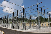
Creating a clear physical disconnection point (Core: Safe isolation)
Limitations of circuit breakers: Although circuit breakers can interrupt huge load currents and short-circuit currents, their contacts are internal, making it impossible to visually determine from the outside whether they are truly disconnected. Even in the "open" state, there may still be a weak electrical connection or breakdown risk between the moving and stationary contacts due to insulation degradation, mechanical failure, etc.
The role of knife switches: Disconnecting switches have a simple structure and a clearly visible air insulation gap when disconnected. This gap provides a "clear physical disconnection point," allowing maintenance personnel to visually confirm that the circuit has been reliably isolated.
Reasons for front and rear configuration: Circuit breakers are devices that require maintenance and repair. If there is only a knife switch on one side of the circuit breaker, the other side will still be energized when the circuit breaker is being repaired, failing to create a safe "isolation zone." With disconnect switches installed at both ends, the circuit breaker is completely isolated from the energized system, creating a safe working area where neither end is energized.


Facilitates equipment maintenance and grounding (Core: Protecting personal safety)
Erecting grounding wires: In power industry safety regulations, reliable grounding in all directions of potential energization is the most important measure to protect the lives of maintenance personnel. The grounding switch (or a separate grounding switch) of the disconnect switch is used for this purpose.
Procedure: When it is necessary to maintain a circuit breaker or line, the operating sequence is usually:
1. Open the circuit breaker.
2. Disconnect the disconnect switch on the line side.
3. Disconnect the disconnect switch on the busbar side.
4. At this point, both sides of the circuit breaker are isolated from the energized system.
5. Close the line-side grounding switch (grounding the line side).
6. Close the busbar-side grounding switch (grounding the busbar side).
Significance: This ensures that even if someone accidentally closes the disconnect switches on both sides of the circuit breaker, or if induced voltage is generated in the line, the current will be conducted to the ground, thus guaranteeing the safety of maintenance personnel. Without the disconnect switches and grounding function on both sides, this reliable and safe grounding cannot be achieved.
Changing the operating mode to improve power supply reliability
Changing the operating mode to improve power supply reliability (Core: Operational flexibility) Substation busbars and lines also require maintenance. By configuring front and rear disconnect switches, flexible switching operations can be achieved, minimizing the scope of power outages.
Busbar maintenance: When a section of busbar needs maintenance, all circuit breakers connected to that busbar can be switched to another normal busbar through a "busbar switching" operation, achieving busbar de-energization without interrupting the load. This requires the coordinated operation of the disconnect switches on both sides of the circuit breaker.
Circuit breaker maintenance: When a circuit breaker itself needs maintenance, the bypass busbar (if available) and bypass circuit breaker can be used. By operating the disconnect switches, the load can be transferred to the bypass circuit breaker, achieving "circuit breaker maintenance without interrupting line power." This also relies on careful configuration of disconnect switches.

Establishing a Clear Operating Sequence (Preventing Accidental Interlocking)
Electrical operations have strict "five-prevention" requirements, one of the most important of which is "preventing the operation of disconnect switches under load."
Disconnect switches lack arc-extinguishing capabilities and must never be operated under current. The presence of a circuit breaker provides a safety guarantee for operating the disconnect switch.
The standard power outage operating sequence is: first open the circuit breaker → then open the load-side disconnect switch → finally open the power-side disconnect switch.
The power restoration operating sequence is the reverse: first close the power-side disconnect switch → then close the load-side disconnect switch → finally close the circuit breaker.
This "circuit breaker-disconnect switch-disconnect switch" structure, in terms of electrical interlocking and operating ticket system, enforces a clear and safe operating procedure, greatly reducing the risk of misoperation.
Illustration and Analogy
Imagine an appliance in your home (such as an air conditioner):
The circuit breaker is like the air conditioner remote control, allowing you to easily turn the air conditioner on and off (operation under load).
The disconnect switch is like a wall socket. When you need to clean the inside of your air conditioner or perform maintenance, simply turning it off with the remote control is not safe. You must unplug it to create a visible, physical disconnect point to ensure safe operation.
The front and rear disconnect switches are like having a plug at each end of the air conditioner's power cord, plugged into a wall socket and an air conditioner socket respectively. This allows you to safely and completely isolate the air conditioner (circuit breaker) from the system.
In summary
The configuration of disconnect switches at both ends of a substation circuit breaker is a concentrated embodiment of the power system's "safety first" and "reliable power supply" design principles. Its main functions are:
1. Safety isolation: Creating a visible and reliable electrical isolation point for maintenance.
2. Safety grounding: Providing reliable grounding protection for the maintenance area to prevent electric shock.
3. Flexible operation: Supporting various switching operations, reducing the scope of power outages, and improving system reliability.
4. Sequential interlocking: Enforcing a safe operating sequence to prevent misoperation.
This is a standardized and mandatory safety configuration developed through long-term practice in the power system.
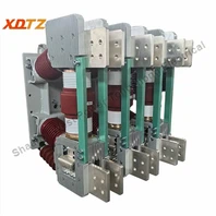
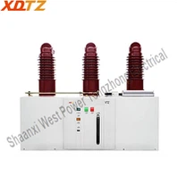
zW32-12 outdoor vacuum circuit breaker
ZW32-12 Outdoor Vacuum Circuit Breaker (hereinafter referred to as "circuit breaker") is a three-phase AC 50Hz outdoor high voltage switchgear mainly used in 10kV outdoor distribution systems of rural and urban networks, as a means of breaking and closing load currents, overload currents, and short-circuit currents; It can also be used in other similar places;Structural features: The circuit breaker consists of three-phase pillars and an operating mechanism, with a simple structure. The pillar adopts epoxy resin solid insulation, which has the advantages of high and low temperature resistance, UV resistance, and aging resistance;Circuit breaker performance: E2-C2-M2.
ZW32-12 Outdoor Vacuum Circuit Breaker has many advanages:
1.Main performance after attaching other devices:
1) Outdoor isolation switch and circuit breaker can be installed to form a body, circuit breaker and isolation switch have a reliable mechanism interlock, with anti-misoperation function.
2) Can be installed with external electronic PT, so that the circuit breaker has an operating power supply and has anti-surge current, overcurrent protection, on Near remote control function.
3) The arrester can be installed, and the arrester can be installed on the power side or the load side according to the needs of the user.
4) Can be combined with the distribution network automation device to form outdoor vacuum recloser, sectioner, intelligent control equipment.
5) Can be used with the column switch remote monitoring system, using GPRS wireless communication, to achieve outdoor real Air circuit breaker remote real-time monitoring, to meet the requirements of distribution automation.
2.Wide range of use: adapt to the harsh environment, the product can withstand minus 25℃ low temperature. Meet the 2000m altitude requirements. Under special requirements, the minimum can reach -40℃, and the special requirements can meet the altitude of 4000 meters.
contact us
 Shaanxi West Power Tongzhong Electrical Co., Ltd.
Contact: Ms.Grace Liu (Director of Sales Department)
Email:xdtz04@westpowerelectric.com
Mobile: +86 18091765882(WhatsApp/Facebook )
Website:https://www.xdtzelectrical.com
Add: Nanpo Village, Chencang Avenue Jintai District Baoji City, Shaanxi Province, China.